Manufacturers requiring a safety integrity level (SIL) 3 solution face several challenges when using SIL 2 components. As Revision 3 of the industrial functional safety standard IEC 61508 is released, new methods must be employed. This article outlines a solution to overcome the challenges of successful SIL 3 implementation and reduce time to market.
There has been a marked uptake in industrial functional safety systems over the last number of years, which has been driven by several factors such as:
An additional driver has been the introduction of stringent requirements for the energy, oil, and gas sectors combined with regulatory obligations.
Before getting into too much detail, let’s take a look at some basic definitions to help readers of all levels better appreciate this article.
Safety is considered to be freedom from unacceptable risk. For example, an unprotected rotating machine on a factory floor would be considered unsafe.
This defines an operation that must be carried out to achieve or maintain safety. The purpose of a safety function is to reduce risk in the system. For example, if that same rotating machine had a light curtain installed in front of it, the safety function would be to detect the broken light beam when a hand passes through it and stop the rotating machine before the hand has time to touch it.
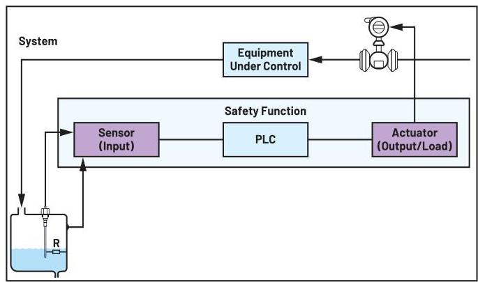
Typically, a safety function has three subsystems. Figure 1 shows a safety system that is used to detect the level of a hazardous liquid and turn off the flow when it is full.
Figure 1. A typical safety function.
This deals with confidence that a system will carry out its intended safety function when required to do so. It is effectively a measure of how confident a functional safety engineer is that the light curtain and stopping safety function of the motor will operate when the light beam is broken.
A system is considered functionally safe if the hardware metrics (random errors), systematic capability (SC), and common cause failures (CCF) do not lead to malfunctioning of the safety system, injury or death in humans, damage to the environment, nor loss of production.
Now with some of the basic safety definitions explained, let’s consider some functional safety standards that must be adhered to when designing a functional safety system and what benefits they bring.
When following a functional safety development process like IEC 61508 or ISO 26262 for example, there are many benefits to manufacturers like:
There are many safety standards (see Figure 2), most of which have been derived from the industrial IEC 61508 standard. It is worth noting that 90% to 95% of the IEC 61508 requirements are similar across all standards.

Figure 2. Safety standards.
This article will focus on IEC 61508 for industrial applications and specifically how to design a SIL 3 solution with SIL 2 components using identical redundancy.
No matter how reliable a system is, systems will eventually fail! Two common failure types are systematic and random. See Figure 3.

Figure 3. Systematic and random failures.
Redundancy is effectively having a spare or redundant path that is able to carry out the intended safety function in case a fault occurs within the safety system. It is worth noting that if a system has a level of redundancy, it does not automatically mean it has high availability. It only has high availability if the redundant path can be turned on or activated automatically. Another term commonly used within the IEC 61508 is called hardware fault tolerance (HFT). An HFT of N means the N + 1 is the minimum number of faults that could cause a loss of the safety function. It is worth pointing out that no account shall be taken of other measures that may control the effects of faults such as diagnostics. HFT is effectively a means to ensure the hardware is robust against failures while allowing you to trade off HFT vs. SFF. See Table 1.
Table 1. Hardware Fault Tolerance
| Safe Failure Fraction of an Element | Hardware Fault Tolerance | ||
|---|---|---|---|
| 0 | 1 | 2 | |
| <60% | Not allowed | SIL 1 | SIL 2 |
| 60% to <90% | SIL 1 | SIL 2 | SIL 3 |
| 90% to <99% | SIL 2 | SIL 3 | SIL 4 |
| >=99% | SIL 3 | SIL 4 | SIL 4 |
SIL describes the integrity of a safety function and the relative level of risk-reduction provided. IEC 61508 specifies four SILs, SIL 1 having the lowest level of safety integrity and SIL 4 the highest level of safety integrity. Table 2 compares industrial IEC 61508 safety levels (SIL) to the automotive (ISO 26262) safety levels (ASIL) and the avionics safety levels. Note these are only approximate comparisons.
Table 2. Various SIL Levels
| IEC 61508 | ISO 26262 | Avionics |
|---|---|---|
| SIL 1 | ASIL A | D |
| SIL 2 | ASIL B | C |
| SIL 3 | ASIL C/D | B |
| SIL 4 | A |
As the SIL level increases in number (from SIL 1 to SIL 4), the allowed failures in time (FIT) decreases. One FIT equates to one failure per billion (1e9) hours of operation. 1e9 hours ~ 100,000 years! It is worth pointing out that no device will last one billion hours of operation, but if you operate 100,000 devices for one year you can expect one random hardware failure in that time. Safe failure fraction (SFF) is a calculation of the total safe plus dangerous detected faults compared to the total faults in a safety function.
Table 3 shows the link between safe failure fraction (SFF) and SIL for a hardware fault tolerance of zero (HFT = 0).
Table 3. SIL and SFF
| SIL | SFF | High Demand Rate Dangerous Failures Per Hour | Theoretically Allowed Dangerous Failures |
|---|---|---|---|
| 1 | 60% | 1e-5 (10,000 FIT) | 1 dangerous failure every 10 years |
| 2 | 90% | 1e-6 (1,000 FIT) | 1 dangerous failure every 100 years |
| 3 | 99% | 1e-7 (100 FIT) | 1 dangerous failure every 1,000 years |
The problem for many designers employing functional safety, specifically those designing with ICs, is that it can be difficult and expensive to achieve certification along with the very real risk of noncompliance. A system-level FMEDA must be created, and they must treat ASICs as black boxes as they don’t know the:
As a result, designers must be overly conservative in their FIT calculations and overly safe in other parts of their safety system in order to achieve their overall SIL target. This generally means the use of external diagnostics like an external ADC. The problems with this are:
To compound these problems, there is a new version of IEC 61508 standard coming out (Revision 3).
Currently planned changes in IEC 61508 Revision 3 include explicit warnings about the use of on-chip diagnostics to detect failures on the same chip unless the IC was developed in compliance to IEC 61508. It is also planned to include requirements similar to automotive ISO 26262 latent fault metric. In addition to a kind of SFF for diagnostic functions, the diagnostic circuiting will also have an SC requirement.
The ADFS5758 is a single-channel, 16-bit current out DAC with integrated dynamic power control (DPC), and internal reference along with numerous on-chip diagnostics. Figure 4 shows the block diagram.
Takes a digital input code and produces an output current to within +/-2.5% full-scale range (FSR).
See Figure 5 for a copy of the TUV Rheinland functional safety certificate for the ADFS5758.

Figure 4. ADFS5758 block diagram.

Figure 5. ADFS5758 functional safety certificate.

Figure 6 shows the ADFS5758 being used in a typical safety application.
Figure 6. Typical application using the ADFS5758.
For a system to meet SIL requirements, then both the hardware metrics (also known as architectural constraints) and the SC must meet the SIL target.
Placing two SIL 2 elements (identical or diverse) in parallel allows a customer to achieve a higher SIL 3 level from a hardware metrics perspective. See Figure 7.

Figure 7. Using two SIL 2 elements to achieve a SIL 3 solution for hardware metrics.
Redundancy can be achieved by using either diverse (different) elements or identical elements.
Using identical elements with the same SC does not improve the overall SC as they are both prone to the same CCF-like temperature spikes or voltage drops and the same fault could bring down both elements. See Figure 8.

Figure 8. Using identical elements does not increase SC.
Using diverse elements in a redundant configuration increases the overall system capability. See Figure 9.

Figure 9. Using diverse elements increases SC.
The reason for this is that since the two elements are diverse or different, the same fault is unlikely to take both elements down at the same time. The problem with this method is that it can be costly to use diverse elements in a safety system as the workload to design in and test increases significantly. Ideally what is required here is a way to use two identical elements to meet both the SC and random or hardware metrics for the functional safety requirements.
If an element could be employed in the system that was developed to a system capability one level higher than the SIL of the element, then two identical elements can be used in a safety system to provide redundancy along with increasing the overall system capability. See Figure 10 for an example.

Figure 10. Example using identical redundancy to achieve SIL 3.
Since the ADFS5758 was developed to an SC one level higher than the hardware metrics, it can be used to design a SIL3 analog output module even though it is only certified to SIL 2 for hardware metrics or random faults.
When using the certified ADFS5758 within a safety system, there are numerous advantages:
Along with the above advantages, the ADFS5758 allows for the use of SIL 2 components to design a SIL 3 solution using identical redundancy.
Brian Condell is a product applications engineer working on IO-Link within Industrial Connectivity and Control at Analog Devices based in Limerick, Ireland. Brian started working in ADI in 1997. He graduated from the University of Limerick in 2003 with an honors degree in electrical engineering. He has over 25 years of experience across the semiconductor industry within various roles from FAB maintenance to IC layout, analog design, functional safety, and more recently, applications. He is a certified functional safety engineer (by TUV Rheinland) for HW/SW Design for IEC 61508.