This article explores the implementation of isolated and bidirectional DC-to-DC power transfer by adapting a dedicated digital controller to work in reverse power transfer (RPT), in addition to its standard forward power transfer (FPT) function. System modeling, circuit design and simulation, and experimental work are presented to validate the theoretical concepts. The application demonstrates levels of conversion efficiency above 94% consistently in both energy transfer directions.
Modular battery-based energy storage systems (ESSs) are key technologies for the construction of a green energy ecosystem, as they assist the effective utilization of renewable electricity. An increasingly popular application are second-life battery ESSs. In this submarket, up to 80% of the discarded batteries are expected to be repurposed into ESSs for stationary grid services, hence increasing the useful life of batteries from 5 years up to 15 years. These systems are expected to add up to 1 TWh to the grid capacity in 2030.¹ This emerging application is bound to gain more importance within the energy market in the near future.
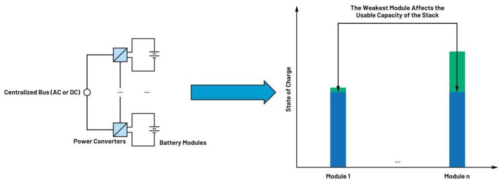
A typical implementation consists of different stacks of battery modules transferring their energy to the centralized AC or DC buses (for some form of subsequent energy dispatchment to loads) via power converters. The challenge with this type of system is due to each module having different chemistries, capacities, and ageing profiles. In a traditional modular topology, the weakest module affects the total usable capacity of the full stack (Figure 1).

Figure 1. The challenge with modular ESSs.
To tackle this limitation, in the architecture shown in Figure 2 the energy in the stack is transferred to a common, intermediate DC bus via individual DC-to-DC converters for each battery module. This energy is then used to support a centralized medium voltage (MV) AC or DC bus via a main power converter. The voltage and power levels in Figure 2 have been chosen based on typical figures from ESSs in the market: 48 V battery modules, 400 V (DC) intermediate DC buses, more than 20 kW (high power) main power converters, and up to 1500 V centralized buses.²
In Figure 2, because the ground references of each module in the stack are different, isolation is needed to implement the individual DC-to-DC converters for each battery module. In addition, for supporting hybrid systems like second-life battery ESSs, each of these converters must also be able to transfer power bi-directionally. In this way, independent charge/discharge of each module and charge balancing can be easily achieved. Therefore, the central blocks of the application herewith discussed are DC-to-DC converters that are at the same time isolated and bidirectional.
Over the following sections, dedicated digital controllers for power conversion are shown to be a good alternative for a safe and reliable implementation of the required type of DC-to-DC converter by adapting these controllers (usually built for unidirectional power transfer only) to bidirectional operation.

Figure 2. A modular battery-based ESS.
For the control of the switching devices in high power DC-to-DC converters (larger than 1 kW), digital control is the current standard in industry, and it is typically based around microcontroller units (MCUs). Despite this, an increased focus on functional safety (FS) across industrial applications could favor the case for using dedicated digital controllers instead. From the system design perspective, an easier FS certification is particularly beneficial in modular implementations as it facilitates the design process and, therefore, reduces the overall time to revenue. Some of the reasons that favor the case of dedicated digital controllers over MCUs are outlined next.


Figure 3. Power conversion topology simulation: (a) model and (b) efficiencies, in standard operation.
The ADP1055 by Analog Devices is a digital controller especially built for isolated DC-to-DC high power conversion and offers a range of features for improved efficiency and safety. These functions include programmable overcurrent protection (OCP), overvoltage protection (OVP), undervoltage lockout (UVLO), and overtemperature (OTP). Like many equivalent off-the-shelf parts in the market, this controller is designed for energy transfer in one direction only — that is, FPT. To achieve a bidirectional operation, the application with the controller must be adapted to work also in RPT. The next section will explore one important aspect in both FPT and RPT modes, which is necessary to understand prior to the process of adaption. This is the efficiency of the target DC-to-DC converter.
Among the different technologies available for isolated and bidirectional power transfer in DC, the architecture in Figure 3a is one of the most used commercially due to its simplicity of implementation.⁵
Table 1. Simulation Study Parameters
| Circuit Parameter | Value |
|---|---|
| Rated DC Bus Voltage | V_BUS = 400 V (DC) |
| Rated Battery Voltage | V_BATT = 48 V (DC) |
| Switches MA, MB, MC, MD | SCT3017AL 650 V/18 A SiC MOSFETs |
| Switches MSR1, MSR2, M_CLAMP | IPB065N15N3 150 V/136 A MOSFETs |
| Transformer | Np/Ns = 6:1; Lm = 50 μH; L_LEAK = 0.1 to 1 μH |
| Choke Inductor | Lo = 50 μH |
| Clamp Capacitor | C_CLAMP = 1 μF |
| Bus Capacitor | Co = 10 μF |
| Switching Frequency | 100 kHz (effective 200 kHz) |
This topology can be seen either as a voltage-fed full-bridge to center-tap synchronous rectifier in FPT, or as a current-fed push-pull converter to full-bridge synchronous rectifier in RPT. A case study with 400 V (DC) in the primary (DC bus) and 48 V (DC) in the secondary (battery module), for high power levels larger than 1 kW, is depicted to illustrate the common challenges of the application. LTspice® was used to simulate the operation with typical wide band gap (WBG) power devices switching at 100 kHz. The parameters used in simulation are depicted in Table 1.
The results in Figure 3b show a rapid decrease in efficiency for higher power levels when regular hard-switching (HS) PWM is used. This is accentuated when comparing RPT with FPT. To improve operation, two main loss mechanisms are identified, which can be mitigated with the corresponding switching techniques described next.
The implementation of these strategies increased the efficiency of the converter from less than 80% to more than 90% at 5 kW in RPT. Similar efficiencies for both FPT and RPT are predicted by these simulation studies too, as shown in Figure 3b.
To implement these switching functions, the ADP1055 offers six programmable PWM outputs to form the timing of the switches and two GPIOs configurable as active clamp snubbers. Both functions are easily programmed within a user-friendly GUI. The benefits of these and other functions of this digital controller can be further studied in the ADP1055-EVALZ user guide, where the standard FPT application is considered.
Once the mechanisms for achieving viable levels of efficiency have been identified, which are suitable for both FPT and RPT modes in this application, the adaption to RPT is finally explored next.


Figure 4. Primary switches passive-to-active transitions with (a) HS and (b) PS PWM.


Figure 5. Secondary switches drain-to-source voltages (a) without and (b) with active clamping.
In order to demonstrate the operation of the application under study in RPT, a low voltage (LV) experimental setup was created as a proof of concept. This setup was based on the hardware in the ADP1055-EVALZ user guide, originally designed for 48 V_DC to 12 V_DC / 240 W FPT, using the ADP1055 as the main controller at switching frequency f_SW = 125 kHz, as a standard case. The RPT operation adaption then involved adequate hardware and software modifications. Figure 6 (top) shows the proposed signal chain on the hardware side for this task, with the following highlights:

Figure 6. Signal chain to adapt RPT with a dedicated digital controller.
The ADuM4195-based measurement scheme is one of the most important additions to the control loop hardware. Besides a safe 5 kV isolation voltage (from the high voltage primary to the LV control side), broad input range of up to 4.3 V, and around 0.5% accuracy at its reference voltage, the ADuM4195 features a high minimum bandwidth of 200 kHz. This allows faster loop operation for better transient response than the typical shunt regulator and optocoupler solutions, which is essential for the operation of the application at its 125 kHz switching frequency. Figure 7 shows the final experimental setup, with the hardware additions of Figure 6 implemented in an ADuM4195-based measurement daughter card, which was added to the original evaluation board in the ADP1055-EVALZ user guide.

Figure 7. Experimental setup for the RPT proof of concept.
Figure 6 (bottom) also depicts the configuration performed on the software side for RPT adaption. The digital control system was studied in depth. The results are summarized in the descriptive blocks of the process, as follows:

Figure 8. Frequency response of the ADuM4195.
In order to keep the analysis in the Laplace domain, a continuous-time model Gc(s) of Gc(z) was created, according to digital control theory. Thus, a computational delay was added first (× z⁻¹), and the final representation in continuous time was achieved by using: (a) the Tustin approximation (z = (4f_sw + s) / (4f_sw – s)) and (b) the Padé approximation to model the discrete PWM (DPWM) delay (of T_sa/2 = 1/4f_sw), so that:
One of the main observations in this exercise is that if the same control constants as for FPT were used, the response in RPT would be unstable. Hence, a proper design of the final values of the constants in Gc(s) is vital for a reliable operation. Once a stable open-loop transfer function was achieved by design, the controller was transformed back into the digital domain. Figure 9 (left) shows the frequency response of the designed digital filter Gc(z), which can be easily configured graphically with the GUI of the ADP1055 on Figure 9 (right).
The functions for an increased efficiency studied in the previous section (PS PWM with adaptive dead times and active clamping) were also configured. Experimentally, it was observed that to achieve proper ZVS in the active-to-passive transitions for RPT, it was necessary to modify the dead times in the PWM sequence. Namely, the turn-on of the secondary switches was modified to happen before each transition from active to passive intervals to allow for current reversal.⁹
The adaption to RPT was tested successfully with 48 V obtained in the primary from an input of 12 V in the secondary. Outstanding output voltage regulation to load, and to input-voltage changes, respectively of 0.1% and 0.02% relative standard deviation (RSTDEV) were achieved, as shown in Figure 10a. Figure 10b and Figure 10c show the conversion efficiency and the step response to a 50% load change, respectively. The efficiency levels in RPT are similar to FPT mode, with a peak of 94% at midpower range, in both cases. The step response parameters (overshoot and settling time) are (1%; 1.5 ms) in RPT compared to (2%; 800 μs) with FPT. A lower overshoot with a slightly slower settling time are observed, composing a stable transient response. These results verify the validity and success of the design process for adapting the digital controller to work in bidirectional power transfer.
Dedicated digital controllers for power conversion are a good alternative for the implementation of safe and reliable applications within the energy market. This is because, compared to microcontroller devices, they can assist an easier FS certification, which reduces the time to revenue of system-level designs. Because these devices are usually built for unidirectional power transfer, this paper explores their adaption to bidirectional operation. Theoretical models, simulations, and experimental studies demonstrate the application of an isolated bidirectional DC-to-DC converter for battery-based ESSs. The results validate the feasibility of the application, with similar performances achieved for both energy transfer directions.

Figure 9. Digital filter response configured on the ADP1055.


Figure 10. Resulting (a) output voltage regulation, (b) efficiency, and (c) 50% load-step response in RPT mode.
About the Author
Dr. Juan Carlos Rodríguez: He received his B.Sc. degree in electrical engineering from the Ecuadorian Army Polytechnic School (Quito, Ecuador) in 2009, and M.Eng and Ph.D degrees from RMIT University (Melbourne, Australia) in 2011 and 2017, respectively. Following a postdoctoral position at the University of Limerick (Ireland), he joined ADI in 2019 where he has worked in isolated power applications and renewable energy. He has worked in industrial automation, energy harvesting for smart grid and IoT applications, and power electronic conversion for sustainable electricity.